Last December I decided that my next boat project would be a model because I am running out of room for boats on trailers, I’ve built six and still have five of them. Links to blogs describing these boats are listed below on the right.

For some time I have been interested in the long deep keel sailing boats epitomised by the Pilot Cutters from the southwest of England. While browsing these boats I came across the first of Leo Goolden's Tally Ho videos and have been watching them since with ever increasing interest.

My interest in Tally Ho led me to choose her for the model. This will be a working radio controlled model, not a display model.

If you would like to contact me please use the contact form below.


Wednesday 7 August 2019

Tally Ho Sails.

Finally I reached a point where I couldn't wait any longer so I loaded Tally Ho into my 4x4 and took her to a local reservoir. Here she is rigged up but still on the trolley. The deck is temporary; thin ply held in place with gaffer tape and tupperware hatches. Not very elegant but enough to keep the water out while I am still testing the radio control servos, etc.


Between the last post and today I tidied up the (temporary) rigging using the blocks. Here are a couple of photos showing a bit of detail.


The model weighs about 30kg and the trolley adds another 5kg so the whole package is more than I can lift for transporation. I had to build a ramp.


Tally Ho was loaded up and taken to the water. This short video shows what happened - I was by myself and working the camera and RC transmitter was difficult hence the limited video. Thanks to my friend Paul for editing the sky and beach out of the raw video.


I was pleased with this first outing despite the very light wind (almost none). Several things need tweaking:
Ballast needs adjusting, she is sailing down at the bow.
Not much rudder control at low speed under sail made changing tack difficult. Maybe make rudder a bit bigger?
Foresail sheets need to work better. The number 2 is often on the wrong side of the forestay. More wind would fix that.
She wants to round up into the wind. Could this be a result of being down at the bow?


Friday 12 July 2019

Fittings, Spars, Sails, Servos,Trolley, Blocks, Turnbuckles and Rigging.

It's been a few weeks since the last post about my 1/10 scale model of Tally Ho.  A good part of this was spent on long overdue maintenance of my CNC milling machine which, after playing up in irritating ways for a while, burned out a motor. I thought it would take a couple of days to disassemble, clean and reassemble but it took 2 weeks! Then the computer that drives it failed; having sourced a new PC the keyboard failed. It's working now - here's a photo of the mast crane for the throat halyard.


The spars now have several coats of varnish, here they are hanging in the sun.


I did some temporary rigging and still have a way to go but the mast is standing.

Here's a photo of the boat with sails. Again their rigging is all temporary. bits of wire and string holding them in place, but with a fan providing a breeze they look OK and as if they will move the boat along.


In the left hand photo above there are three servos with arms. The aft one is for the rudder; a lime from each end of this arm pull the tiller to port or starboard. The forward one is for the jibs; lines from this will pull in the sheets for the two foresails. The centre servo will operate the mainsheet. Lines from the servos arms will pass through tubes in the deck. Testing shows that the rudder and foresails will work but there are two problems with the mainsheet. With a fan blowing on the mainsail (approximately 7 or 8 knots of breeze) the servo struggles to pull in the sail. With no breeze to take the sheet out it falls in a heap and gets tangled. As an alternative to the arm winch I set up a drum winch with an endless loop around a pulley.

Here area couple of short videos of this working, first with wind and then with no wind. The blue line is the mainsheet. with wind on the sail the sheet runs out nicely and the winch can pull the sail in.


With no wind on the sail the sheet goes slack and falls on the brown paper. One way of overcoming this problem is to use a length of hat elastic to take up the slack. I've tried this and while it can solve the problem eventually the servo has to stretch the elastic and this is wasted effort. For the time being I will use some clear plastic sheet, in place of the brown paper, to stop the slack sheet getting caught up on anything below it.

A better solution is to have a winch that doesn't let out the mainsheet unless there is tension on the sheet. A mechanism like this is described in the Jolie Brise pages. This is more time consuming to make and so I will try the endless loop approach described above first.

Because the model will be heavy I've been working on a trolley to move it around. I will need ramps to get it up and down onto the work bench and into my vehicle. Here it is raised up so I can work on it. The mast will need to be lowered when moving the boat on the trolley and there is barely enough room to raise the mast under the workshop ceiling!


While waiting for the paint to dry on the trolley I spent some time making blocks. All single blocks for the time being, some with working sheaves and some "dummies" for appearance. Here's the prototype dummy block.

The blocks have been varnished and here's a group photo with the sheaves waiting for the varnish to harden up a bit before assembly.

I've also been working on some turnbuckles. Here's the prototype. The body is turned from a 40 mm long piece of hexagonal brass bar  The threads are 3mm diameter and 3mm taps are short so I drilled a 3.5mm hole 35mm from one and and then silver soldered a 5mm long plug in the open end of the hole. Now the ends of the body can be drilled and tapped for the 3mm screws, right hand thread one end left hand the other.

The screws shown here are turned from 6mm square bar turned down to 3mm and threaded, again left and right hand. Holding the square end in the lathe chuck and turning it down to 3mm is tedious and quite difficult. Cutting a slot in the outer end if the screw defeated me, I couldn't work out how to hold it securely enough.

The solution was to cut the slot in the end of the bar stock first and then cut off the piece  with the slot and drill and tap it for the screw. A length of threaded rod was then screwed in and silver soldered.

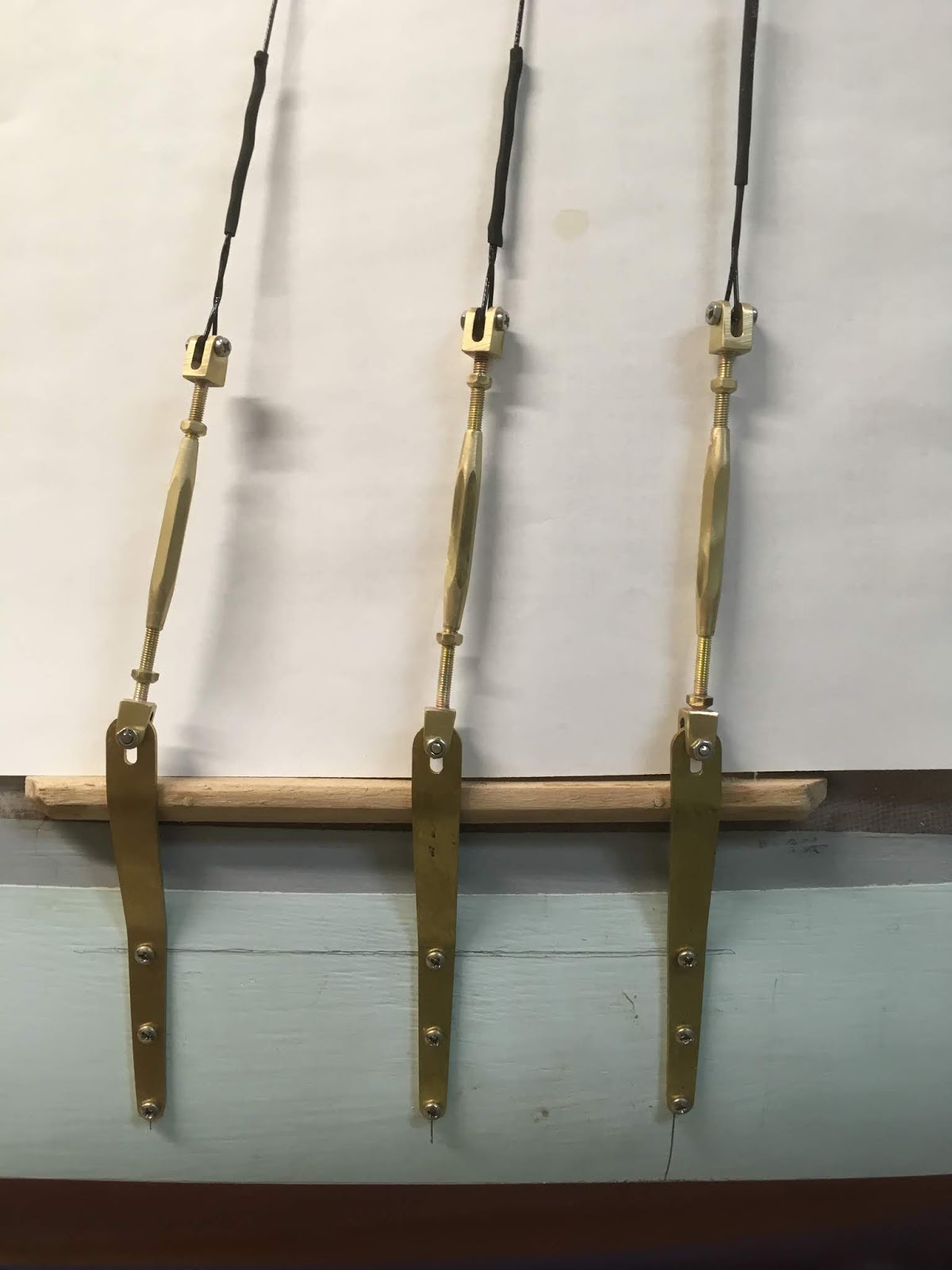
Here are some of the finished turnbuckles. The shrouds and forestay are nylon coated fishing trace wire; I think it looks a bit thin (a bit under a millimetre) but the mast won't fall down!


Sunday 21 April 2019

Change of Direction

At the time of the last post my intention was to install the RC servos etc then build the deck over them leaving access through hatches and finally complete the rigging before launching the boat. It seemed sensible to install the RC stuff while there was nothing above it and this set the order of things. At the last meeting of the local Wooden Boat Association I met a member of another local club called the Triple "S" Model Boat Club, The SSS stands for Sail, Scale and Steam. He has traditional sailing boats and has shown me a couple of them on the water. He advised me to get my boat sailing with rudder control only as a first step to get a feel for how she sails and to get a better idea of what sail control is needed. To do this there needs to be a temporary deck sealed with duct tape or similar plus a jury rig to hold up the sails. This means that the work involved in completing the deck structure, stanchions and bulwarks and the deck planking can be done later.

Before these conversations I had been working on the deck beams and framing for the deck houses. Here is what it looked like as I glued up the various structures, note that they are not actually glued into the hull. From left to right forward companionway, main deck house, aft companionway and cockpit. The deck will eventually be build around the raised sides of the openings and the "houses" fitted as "lids" over the openings.


That's about where the plan changed. I went back to casting lead for the internal ballast. I made a wooden mould to cast trapezoidal bars that could be cut into section to fit between the frames. Here are the two lead bars with a finished piece of ballast at the top left.The lead cuts easily on the badndsaw and the blocks are cleaned up on the sander.


Here a two of the blocks in place. Altogether there are 13 kg of them.


The next step was to make the metal fittings needed for the boat. Even with my small CNC mill this to quite some time to draw and machine them. here they are. From top left in two rows: rudder pintles, gooseneck, mast step, mast ring for cap shrouds, chainplates, support for inboard end of bowsprit, gammon iron, rings for the jib tacks, cranse iron, stemhead fitting and bobstay fitting.I have still to make some turnbuckles.


Here are the rudder pintles in place, temporarily.


And the bowsprit supports.


From the photos it id hard to get a feel for the size of the model. so here is a view of the hull with the mast, bowsprit and boom laid on it with a one metre steel rule. The mast is about 1.5 metres and the boom just over a metre. Click on the image to get it enlarged. The spares are made up of four quarters glued together and then planed to circular sections.


My daughter is going to make up the sails for me so I have been making paper patterns. Here's the main sail with the 1 metre rule laid on it.


I'm struggling a bit over the question of screws, bolts, etc, blocks, shackles, thimbles and cord for rigging. To get these components to look right at 1/10 scale isn't easy and the jury rigged model will probably use inappropriate screws and stuff from the fishing tackle shop. In the long run I might have to make stuff myself for the finished model.

Sunday 31 March 2019

Lead Keel and Painting

Here's where I'm up to today. Read on to see the steps along the way.


There is a photo of the mould for the lead keel in the previous post. I was nervous about melting the lead and pouring it into the mould for a variety of reasons. After a week of sitting in hot sunshine the surface of the mould still felt damp; I decided that the Plaster of Paris is hygroscopic and the high humidity made the surface feel damp. I was also concerned about actually spilling the molten lead and being splashed. Consequently I approached the job wearing heavy clothing, boots, welding gloves and a full face mask. This on a day when the temperature was 37C! The melting was easy, gas stove and old stainless steel saucepan in the open air. The pouring was harder because the saucepan was heavy (obviously), didn't have very good handles (although a pair of multi-grips improved on this) and didn't have a pouring spout. The lack of a spout was the biggest problem and resulted in a somewhat messy pour.


I cut of the flashing around the top with the bandsaw and then flattened the top with the power planer; both dealt with the lead OK although there was a tendency for the lead to "weld" onto the edge of the planer blades.

I made the pattern sightly larger to allow for the shrinkage of the lead as it cooled with the result that the casting was slightly oversize. The excess was removed with the power plane and belt-sander. In the photo above the lead is sitting on the hull as I "fine tuned" the shape. The pitting in the surface is due (I think) to the surface moisture in the mould which became steam and bubbled through the molten lead. Thankfully it didn't cause any splashing.

I drilled holes for fixing screws (bronze) and bedded the casting in place using thickened epoxy. Some more bag and sanding and the hull was ready for the the fibre glass cloth.


Two coats of unthickened epoxy with each coat applied when the previous coat was just still tacky and it looked like the next photo. A third coat with enough sanding filler to give it a creamy consistency completely filed the weave of the cloth and provided a surface that could be sanded flat. The coats of resin were poured on and spread with a squeegee cut from a length on 1.5mm balsa sheet.


The patchwork quilt disappeared under three coats of primer and 3 coats of undercoat followed by a lot of wet and dry sanding.


Then the waterline was marked and taped and 4 coats of satin finish paint sprayed on.


Now to the exciting part. I "launched" the boat into my garden pond to see where she floated and to get a feel for how much internal ballast would be needed to sink her to her waterline. The photo at the start of this post shows Tally Ho floating quite high with no internal ballast added. Adding a  mixture of lumps of lead and  concrete pavers sank her down to her waterline.


Now for some numbers. The bare hull weighs about 12 kg and the internal ballast added 17 kg for a total of 29 kg. It's now clear that I will need a trolley of some sort to transport the completed model to the water. Sure I can carry 29 kg but not when it is a big awkward shaped model boat!

It is interesting to compare my model displacement with the full size displacement given on the original plans, The plans show a displacement of 30 (English) tons or 30481 kg. At 1/10 scale the volume of water being displaced is 1/1000 of the full size boat so my model displacement should be about 30.5 kg. Adding another 1.5 kg of ballast to the model would sink it a bit more but only by a couple of millimeters.

I think it has all worked out according to plan.


Sunday 17 March 2019

Slow Progress!

Progress seems to have been slow but there has been some. I found a suitable propeller and shaft and after some head scratching drilled a hole through the stern post and installed the brass tube making sure the space between the metal and wood was completely filled with epoxy. Here's what it looks like  from astern - Captain Pugwash is a bit on the short side, he's only 5 foot tall including his box!


The propeller is 60 mm diameter which scales out to 24" which is about the size I measure off the plans and looks about the size of the prop that Leo pulled out of the boat in video 7 but it isn't as heavy!

I cleaned up the inside of the hull using sanding disks on a Dremel. It is still uneven but the blobs of epoxy are gone. It now has a coat of epoxy with grey primer over that and looks quite respectable. No one is going to see it when the model is finished!

The outside of the hull was more of a challenge as it has to have a smooth surface. Sanding removed the high spots in the planking and an application of epoxy "bog" (white) filled in the low spots. Sanding and more bog (grey) and more sanding gave it a surface that I'm happy with. It looks a mess at the moment but that will be fixed soon.


The drawing show the stern post cutaway to give clearance for the prop. Leo's videos show that the prop was held away from the stern post by a wooden spacer block. I've chosen to follow the plans with cutouts in both stern post and rudder. Here's what it looks like (I need better hinges!).


I've made a mold for casting the lead keel using the wooden pattern made previously. I used Plaster of Paris because it is easy to work with and readily available. It is taking a long time to dry out (still feels damp after 2 days but in Brisbane's high humidity it is taking longer than expected). If it doesn't dry out in another day or so I will put it in my steam box with a hair dryer - it is too big for the kitchen oven. It has to be dry because moisture and molten lead are a bad combination.


I've begun thinking about how I can control the sails with radio control. Obviously by using servos but just how to do this is not so obvious. The main sheet needs 800 mm of travel as the boom moves from the centre line to just touching the shrouds. There are several ways of handling the main sheet using sail winch servos but getting the 800 mm travel is a problem. The foresails provide a different problem because there are two sails (working foresail and number 2 jib) that need  different amounts of sheet travel using one servo also one sheet has to be let out so the other can be taken in. Of course all of this has been done before but not by me and I am having trouble finding the "how to" information.

The reason for sorting out the sheeting and servo arrangements is that I want to get them installed and working before I start putting the deck on. Once the deck is on access to the inside of the hull will be more difficult unless I can find some tiny assistants.

Next steps are: cast and fit the keel, fibre glass the outside of the hull and put some primer on it, continue working on the sail control.

Saturday 2 March 2019

Planking All Done

 The planking went fairly quickly to begin with because the planks could be put on without any shaping. Eventually one or both ends of the planks had to be shaped. Even then the process was much easier than it would be on a full size boat. I used clamps of various sorts to hold planks while the epoxy set. Mostly though I used staples put in with a hand powered stapler and then pulled out the next day. Inevitably the stapler picked up some epoxy and I killed one stapler.


The next photo shows the last few planks going in on the port side. The staples are clearly visible. This whole process was very sticky. Applying epoxy to the edges of planks and holding them in position was very messy. Fortunately I don't have any allergic reaction to the type of epoxy I use but it will be a few days before my hands are clean again!


Some cleaning up of the excess epoxy has been done (hot air gun and scraper then sandpaper) and the outside part of the stern post is being glued in place.


The outside part of the keel (below the rabbet line) has been glued on and the light coloured pine piece is the pattern for the lead keel.

The hull is now the right way up.


There is something not quite right about the sheer line above the forward cradle; it seems to bulge up but probably only by a couple of millimetres.


At this stage the inside of the hull is a mess with blobs of squeezed out epoxy along the plank joins and at the frames. I'll have a go at cleaning it up but it will be difficult to get access with a scraper so it isn't going to be perfect. Also. the gaps between planks that didn't get filled with epoxy are no more obvious. Can't use oakum and a calking hammer at 1/10 scale so the whole inside of the hull will get painted with epoxy slightly thickened with filler powder to make it slightly less runny.

Tuesday 19 February 2019

The First Steps

Having decided to build a model of the Albert Strange yacht Tally Ho I needed a set of plans. There are small low resolution lines plans on the interent but I wanted something better to use as a starting point. Plans are available from the Albert Strange Association. During the process of ordering the plans I joined the ASA and find that they have an interesting newsletter which is worth reading. The (paper) plans come from the UK and I'm located in Australia. The Christmas postal crunch came along and delayed the plans on their long journey but eventually they arrived.
The lines plan is drawn at a scale of 3/4" to the foot and I needed to change this. I had the lines plan scanned and saved as a JPEG. I have a program on my PC which does raster to vector conversion and produces a DXF file which my 2D CAD program can read. With the lines plan in my drawing package I slowly fitted spline curves to all the lines I would need; that is the body section, various keel lines and the sheer lines.

Somewhere about this point I had to finally decide on the scale for my model. I made a little spreadsheet with the overall dimensions of the original and calculated the model dimensions at various scales.


I wanted this to be a reasonably big model that could sail reasonably well and that is why the table shows scales of 1/8, 1/10 and 1/12. At 1/8 scale the model is quite big (hull 6 ft OAL) and is getting unmanageable in terms of transportation; it would also be quite heavy. At 1/12 scale the size and weight would be less but I was a bit concerned about the potential problem of the ballast ratio. Usually model sailing boats have a deep fin keel with a bulb on the end to provide enough stability for them to carry their sails. At 1/10 scale it is still a big model (hull 4.75 ft) but is more manageable in terms of transportation. It is also the same size as the 1/10 scale Jolie Brise which sails exceptionally well.

So, 1/10 it is. I made individual drawings of all 22 frames with a supporting piece. Here is one of the frames.

Various things can be seen in the above drawing. The hull will be build upside down. The T shaped support for the frame has a notch to align all the frames on a building board. The T shape is 200mm high and the top edge is on the water line. The planking will be 4mm thick and the frames will be cut from 6mm thick plywood. The keel will consist of a 12mm thick plywood spine with solid timber side pieces to provide the necessary shape. After a lot of thought I modified the keel arrangement; in the above the planking extends down to the lead keel making construction more difficult. I chose to cut the keel off at the rabbet line and to run the planking down to the rabbet line. When the hull is complete an outer keel will be added to cover the edges of the planks and the internal keel. Finally the external lead keel will be attached.

The above description is probably a bit confusing but it makes sense to me! If you follow this blog all will become clear.

The frames and their supports were printed out and glued onto a sheet of 6mm plywood. Then each piece was cut out on the bandsaw. This took hours to do and was spread over several days to give my eyes and back some recovery time!

Here are the frames assembled on the building board. At this stage the keel is too high and will be cut back to the rabbet line.


The keel is now finished with the side pieces in place. The frames are glued to the keel and the joints have fillets. I need to say something about how the frames turned out. In a nutshell I should have lofted the boat starting from the original table of offsets and the lines drawing both of which will inevitably contain errors. I'm not being critical, think how how Albert Strange drew the plans: make a half model, measure the offsets, plot these at 3/4" scale and draw fair curves through the points. Refine these curves until satisfied with them. That is what Leo did and one day he might take a new table of offsets from his lofting floor.

Anyway, I took the frame shapes from the original lines plan and rescaled them. Putting a fairing batten across my frames I found some of them were high and some were low by as much as 2mm. I worked on the high ones with a file plus sandpaper and the low ones had packing strips glued on to raise them.


The next problem was that my 6mm plywood frames were a bit floppy and I needed them to be vertical. In the phot below (the hull is on its side) a combination of spacers and Spanish windlasses is doing this until There are a couple of planks on the sheer.


Last photo shows some planks in place. This is something I have not done before and I am sure there is an optimum sequence and techniques for working out how the planks need to be tapered. But this is a model and the planks will bend and twist relatively easily so I will use parallel planks until they have to be shaped. Clamping them is a challenge and will get harder as the space between the planks decreases. I'm having good results using a hand powered stapler. The planks are glued in place with epoxy and this is working well except that the stapler picks up traces of epoxy and may not last the distance!.


This has been a long post because I am catching up on work since the start of the project. I try and post something about weekly but it will depend on what's happening, The planking will take a while and then there is painting neither of which are very photogenic!