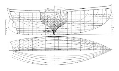
The lines plan is drawn at a scale of 3/4" to the foot and I needed to change this. I had the lines plan scanned and saved as a JPEG. I have a program on my PC which does raster to vector conversion and produces a DXF file which my 2D CAD program can read. With the lines plan in my drawing package I slowly fitted spline curves to all the lines I would need; that is the body section, various keel lines and the sheer lines.
Somewhere about this point I had to finally decide on the scale for my model. I made a little spreadsheet with the overall dimensions of the original and calculated the model dimensions at various scales.
I wanted this to be a reasonably big model that could sail reasonably well and that is why the table shows scales of 1/8, 1/10 and 1/12. At 1/8 scale the model is quite big (hull 6 ft OAL) and is getting unmanageable in terms of transportation; it would also be quite heavy. At 1/12 scale the size and weight would be less but I was a bit concerned about the potential problem of the ballast ratio. Usually model sailing boats have a deep fin keel with a bulb on the end to provide enough stability for them to carry their sails. At 1/10 scale it is still a big model (hull 4.75 ft) but is more manageable in terms of transportation. It is also the same size as the 1/10 scale Jolie Brise which sails exceptionally well.
So, 1/10 it is. I made individual drawings of all 22 frames with a supporting piece. Here is one of the frames.
The above description is probably a bit confusing but it makes sense to me! If you follow this blog all will become clear.
The frames and their supports were printed out and glued onto a sheet of 6mm plywood. Then each piece was cut out on the bandsaw. This took hours to do and was spread over several days to give my eyes and back some recovery time!
Here are the frames assembled on the building board. At this stage the keel is too high and will be cut back to the rabbet line.
The keel is now finished with the side pieces in place. The frames are glued to the keel and the joints have fillets. I need to say something about how the frames turned out. In a nutshell I should have lofted the boat starting from the original table of offsets and the lines drawing both of which will inevitably contain errors. I'm not being critical, think how how Albert Strange drew the plans: make a half model, measure the offsets, plot these at 3/4" scale and draw fair curves through the points. Refine these curves until satisfied with them. That is what Leo did and one day he might take a new table of offsets from his lofting floor.
Anyway, I took the frame shapes from the original lines plan and rescaled them. Putting a fairing batten across my frames I found some of them were high and some were low by as much as 2mm. I worked on the high ones with a file plus sandpaper and the low ones had packing strips glued on to raise them.
The next problem was that my 6mm plywood frames were a bit floppy and I needed them to be vertical. In the phot below (the hull is on its side) a combination of spacers and Spanish windlasses is doing this until There are a couple of planks on the sheer.
Last photo shows some planks in place. This is something I have not done before and I am sure there is an optimum sequence and techniques for working out how the planks need to be tapered. But this is a model and the planks will bend and twist relatively easily so I will use parallel planks until they have to be shaped. Clamping them is a challenge and will get harder as the space between the planks decreases. I'm having good results using a hand powered stapler. The planks are glued in place with epoxy and this is working well except that the stapler picks up traces of epoxy and may not last the distance!.
This has been a long post because I am catching up on work since the start of the project. I try and post something about weekly but it will depend on what's happening, The planking will take a while and then there is painting neither of which are very photogenic!


Just brilliant - I can follow Leo and you now - good luck with the build.
ReplyDeleteDelightful. I look forward to following you. Thank you for allowing us to watch and share. I've already shared with a guy who sails with me. Where will your ship sail?
ReplyDeleteIf only Leo's boat would build so fast.
ReplyDeleteBrilliant project. Suggest using a Dremel type tool to clean up epoxy squeeze out where it is hard to access. Use a long thin drill bit with a little sand paper fixed to the end - whatever I really admire the job.
ReplyDeleteAwesome job. Like to see it when it's finished.
ReplyDeleteIs there a youtube channel to follow the build of this as i am considering doing one myself.lewis
ReplyDeleteHi there, I think you've done what I wanted to try, get a CAD drawing of the hull.
ReplyDeleteI wanted to 3D print a half hull. Do you have an STL file you could share?
Coincidentally, I'm also from Australia, originally, but now in the USA